
SLF250
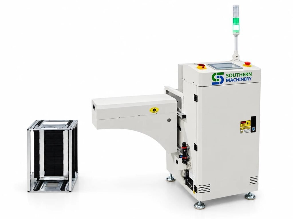
SLF250 L-Type PCB Magazine Loader
SLF250 L-type PCB magazine loader: 50×50–330×250 mm boards, 900±20 mm transfer height, PLC with pneumatic pusher, SMEMA. Plan your SMT line entry with us.
Specify your line entry.
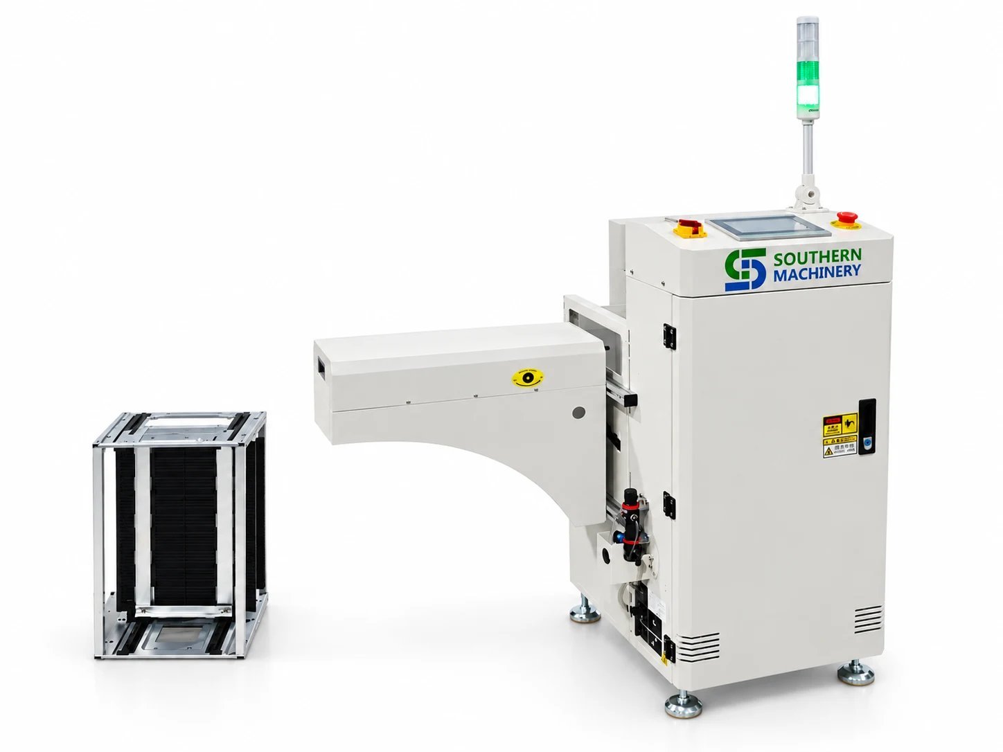
The SLF250 is an L-type magazine loader for PCB supply at a production-line entry. It handles boards from 50 × 50 to 330 × 250 mm, with manual width adjustment and pneumatic pushing under PLC control.
Plan it around your board range, magazine and the interface to the next machine.
Values describe the SLF250 configuration on its product page; options are confirmed in the quotation.
At a glance
- 50 × 50 – 330 × 250 mm — PCB range
- 900 ± 20 mm — transfer height
- 1150 × 700 × 1250 mm — machine size (L × W × H)
- 355 × 320 × 563 mm — magazine size, one magazine included
- ≤ 2 kg — board load
- PLC + pneumatic — control and board pusher
What a loader decision has to settle
A loader is only as good as its fit to the board, the magazine and the next machine.
- Board fit: PCB thickness, edge clearance and component interference affect the magazine and pushing arrangement.
- Interface: The downstream request signal and ready conditions must be agreed, or the loader waits or transfers at the wrong time.
- Access: Magazine insertion, width adjustment, cabinet door and air supply need space around the machine.
- Height vs clearance: Transfer height and signal-tower clearance answer different questions.
SLF250 features — Feature, Advantage, Benefit
Four points from the SLF250 configuration.
Board range: 50 × 50 to 330 × 250 mm
Board load up to 2 kg.
- Feature: Supports PCBs from 50 × 50 to 330 × 250 mm and board loads up to 2 kg.
- Advantage: One loader covers small and mid-size boards.
- Benefit: Fewer loader variants across the line.
Key points: 330 × 250 mm max · ≤ 2 kg · Manual width
Pusher: Pneumatic pusher, PLC control
Board transfer to the line.
- Feature: Pneumatic board pushing with PLC control; manual width adjustment sets the selected PCB format.
- Advantage: Simple, robust transfer from magazine slot to conveyor.
- Benefit: Boards are fed on machine timing instead of by hand.
Key points: PLC · Pneumatic pusher · Left to right
Interface: SMEMA interface
Female connector, 3 m cable.
- Feature: SMEMA interface with a machine-side female connector and a supplied 3 m mating cable.
- Advantage: Request and ready signals are exchanged with the downstream machine.
- Benefit: The loader transfers only when the next machine is ready.
Key points: SMEMA · 3 m cable · 900 ± 20 mm
Magazine: L-type magazine arrangement
One 355 × 320 × 563 mm magazine included.
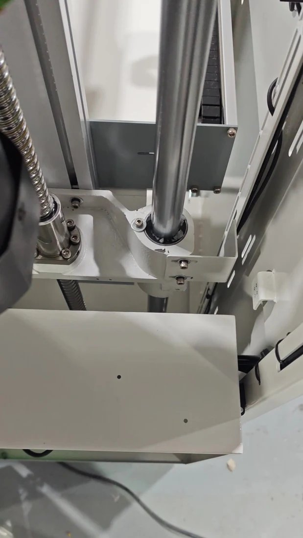
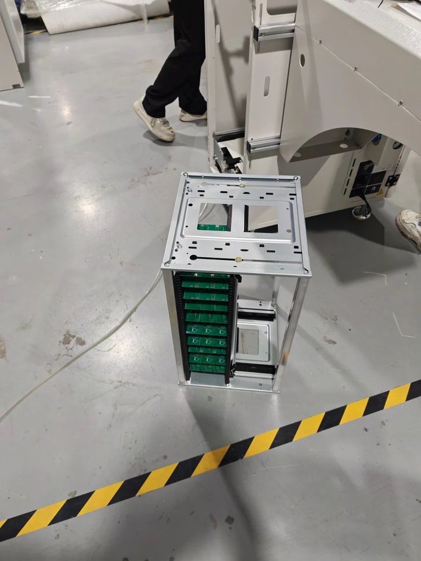
- Feature: L-type magazine arrangement with control cabinet and vertical lift assembly; one 355 × 320 × 563 mm magazine included.
- Advantage: Existing magazines can be checked for fit with your current setup.
- Benefit: Magazines and boards stay compatible across repeat orders.
Key points: L-type · Vertical lift · Magazine included
SLF250 configuration at a glance
No SLF250 page exists on www.smthelp.com; values are from the SLF250 product page. SLD250-family documents are related reference material only.
Configuration
| Parameter | SLF250 |
|---|---|
| PCB range | 50 × 50 – 330 × 250 mm |
| Transfer height | 900 ± 20 mm |
| Machine size (L × W × H) | 1150 × 700 × 1250 mm |
| Magazine size | 355 × 320 × 563 mm (one magazine included) |
| Board load | ≤ 2 kg |
| Width setting | Manual adjustment |
| Control / pusher | PLC / pneumatic pusher |
| Power | AC 220 V, 50–60 Hz |
| Direction | Left to right |
| Line interface | SMEMA, machine-side female connector, 3 m mating cable |
Verify signal-tower clearance in the installation layout. Configuration-specific details are confirmed in the quotation.
Compatibility and interfaces: SMEMA, PLC, Pneumatic pusher, L-type magazine
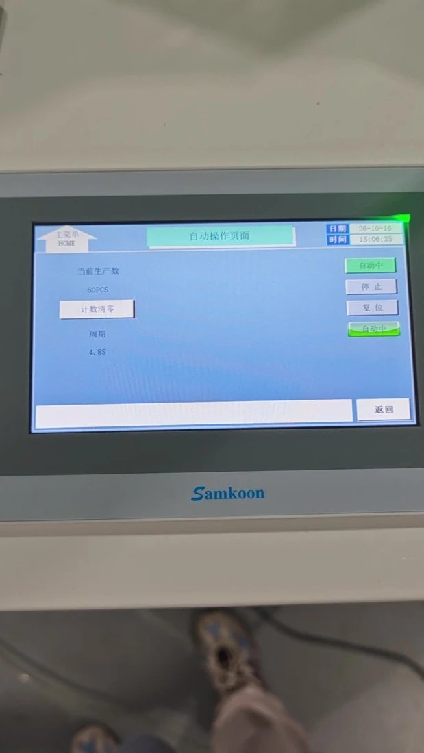
SLF250 machine and details
Watch the equipment
Interactive 3D demo
Open the interactive 3D model of the SLF250 loader (opens in a new tab).
Plan the handoff before installation
- 1 · Share the board — PCB size, thickness, board edge and component clearance.
- 2 · Check the interface — Direction, transfer height and the adjacent equipment.
- 3 · Review the layout — Footprint, access space, magazine and utilities.
- 4 · Approve the configuration — Specification and acceptance checks agreed in writing, with a loading trial before shipment.
Frequently asked questions
What PCB range does the SLF250 handle?
50 × 50 to 330 × 250 mm boards with a board load up to 2 kg. Confirm thickness and edge clearance for your application.
Is width adjustment automatic?
No. This configuration uses manual width adjustment; the pusher is pneumatic and the control is PLC.
Which dimensions should be used for layout?
L1150 × W700 × H1250 mm for the machine and 355 × 320 × 563 mm for the magazine. Confirm signal-tower clearance in the installation layout.
Why do some documents say SLD250?
SLD250-family documents are related reference material. The SLF250 configuration stated here takes precedence.
How does it connect to the next machine?
Through a SMEMA interface with a machine-side female connector and a 3 m mating cable. Share the downstream machine model so the interface check can be part of acceptance.
Engineering Review
Send PCB details for a practical machine recommendation.
Useful details: PCB type, board size, component list, monthly volume, current worker count, line layout and target automation goal.
Next step: Tell us your PCB dimensions, magazine or line interface, transport direction and required quantity.
Engineering Review
Send PCB details for a practical machine recommendation.
Useful details: PCB type, board size, component list, monthly volume, current worker count, line layout and target automation goal.
Tell us your PCB dimensions, magazine or line interface, transport direction and required quantity.