
S4000
S4000 Axial Auto Insertion Machine
S4000 axial insertion machine: 20,000 CPH nominal, 5–22 mm lead span, axial parts and jumper wire, servo positioning <0.001 mm, vision. Free demo.
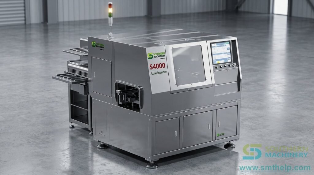
Take the axial band off the hand-insertion bench.
The S4000 inserts taped axial components (resistors, diodes) and jumper wire into through-holes, then cuts and clinches the leads in one cycle. Axial parts and jumper wire can run in the same program, or jumper wire can be inserted on its own.
Precision ball-screw and AC servo positioning, a vision system for positioning and insertion alignment, an integral cast-iron frame and off-line or in-line operation make it the axial half of a Southern Machinery THT line.
20,000 CPH nominal speed (www.smthelp.com). The 2024 brochure also prints a 10,000 CPH actual speed; your own board rate is confirmed on a free demo run.
At a glance
- 20,000 CPH — nominal insertion speed
- 10,000 CPH — actual speed printed in the 2024 brochure
- 5–22 mm — component lead span
- 0°/90°/180°/270° — insertion angles
- <0.001 mm — positioning accuracy (ball-screw + AC servo)
- 1 operator — does the work of forty manual insertion operators, per Southern Machinery
Why axial parts are still inserted by hand
SMT took the chips and radial inserters took the capacitors. What is usually left on the bench is the axial band: resistors, diodes and the jumper wires that tie a board together.
- Four hand movements per part: Pick, check polarity, bend the leads to the hole pitch, insert and clinch, repeated for every axial part.
- Jumper wire is slow by hand: Cutting, forming and placing wire links is tedious and easy to get wrong.
- Mixed spans: Boards carry parts at several lead spans, so hand-forming tools keep changing.
- Insertion defects reach the wave: Missing or mis-inserted leads are found after soldering, when rework costs most.
- Headcount scales with volume: Every extra order adds operators instead of machine hours.
- Data gaps: Manual benches leave no insertion record for MES or traceability.
Built for axial and jumper wire insertion — Feature, Advantage, Benefit
Five functions that move the axial band onto a machine.
Speed: 20,000 CPH nominal
Axial and jumper wire in one cycle.
- Feature: Nominal insertion speed of 20,000 CPH; the 2024 brochure prints 10,000 CPH as the actual speed.
- Advantage: The insertion head cuts, forms, inserts and clinches in one continuous cycle instead of four hand movements.
- Benefit: One operator covers the output of a manual insertion bench and the axial band stops limiting the line.
Key points: 20,000 CPH nominal · 10,000 CPH actual (brochure) · Off-line or in-line
Jumper wire: Jumper wire without taping
Dedicated jumper axis.
- Feature: Jumper wire is straightened and fed by its own axis and inserted directly without a taping step; dual jumper feeders handle two wire specifications such as 0.5 mm and 0.6 mm, from reel or drum packages.
- Advantage: Axial parts and jumper wire can be mixed in one program, or jumper wire inserted on its own.
- Benefit: Southern Machinery documents a saving of one third of the jumper wire, and no separate wire-forming station.
Key points: Dual jumper feeders · Reel or drum wire · Mixed with axial parts
Precision: Ball-screw, AC servo and vision
Positioning accuracy <0.001 mm.
- Feature: Imported precision ball-screws and an AC servo system position the board to <0.001 mm; a vision system handles positioning and insertion alignment with multi-point MARK correction.
- Advantage: Hole positions are corrected on every board, not only once per program.
- Benefit: Fewer bent or folded leads; the series manual states an insertion defect rate below 500 PPM.
Key points: <0.001 mm positioning · Vision alignment · <500 PPM defect rate
Clinch: Adjustable cut and clinch
Lead span 5–22 mm.
- Feature: Component lead span from 5 to 22 mm; clinch lead angle adjustable from 0° to 45° and clinch lead length from 1.28 mm (0.050″) to 1.80 mm (0.071″), measured from the centre of the insertion hole.
- Advantage: The clinch is matched to the board and the component instead of to an operator’s hand.
- Benefit: Parts stay seated through wave soldering with fewer touch-ups.
Key points: 5–22 mm span · 0–45° clinch angle · 1.28–1.80 mm clinch length
Software: USB / Excel programming and MES data
Programs from Excel data.
- Feature: Programs are imported over USB in Excel format and can be edited online or offline; the Windows-based control writes production data to an MES-compatible folder.
- Advantage: A protection program guards against USB data transmission errors and PCB damage.
- Benefit: New boards are programmed quickly and production counts are logged automatically.
Key points: USB / Excel · Online and offline editing · MES-compatible data
Key specifications for project evaluation
Values from www.smthelp.com (S4000 Axial Auto Insertion Machine page); items not published there come from the 2024 S4000 brochure and series manual where those documents agree.
Insertion
| Parameter | S4000 |
|---|---|
| Insertion speed | 20,000 CPH nominal (10,000 CPH actual speed printed in the 2024 brochure) |
| Components | Taped axial components (resistors, diodes and other braided parts) and jumper wire; axial parts and jumper wire mixed or jumper wire alone |
| Component lead span | 5–22 mm |
| Insertion angle | 0°, 90°, 180°, 270° |
| Clinch | Lead angle adjustable 0–45°; lead length adjustable 1.28 mm (0.050″) to 1.80 mm (0.071″) |
| Positioning | Imported precision ball-screw and AC servo system, positioning accuracy <0.001 mm |
| Vision | Vision system for positioning and insertion alignment; multi-point MARK correction |
| Lead diameter | 0.3–0.8 mm |
| Component height | 15 mm standard, customisable on request |
| Jumper wire | Dual jumper feeders for two wire specifications (e.g. 0.5 mm and 0.6 mm); reel or drum packages |
| Option | Second-level component centering mechanism |
| Insertion defect rate | <500 PPM |
Machine and utilities
| Parameter | S4000 |
|---|---|
| Operation | Off-line or in-line; automatic PCB loading/unloading, left-to-right or right-to-left; manual version available |
| PCB thickness | 0.79–2.36 mm |
| Frame | Integral cast-iron machine frame |
| Data input | USB port, Excel format; online and offline program editing |
| Control | Industrial PC with bus-based (EtherCAT) multi-axis motion control; Windows-based, Chinese / English interface |
| Smart factory | MES-compatible production data; 4G IoT and black-box data logging listed as available |
| Power | Single-phase AC 220 V, 50/60 Hz, 1.6 kW |
| Air consumption | 0.3 m³/min |
| Ambient temperature | 5–28 °C |
| Noise | 65–75 dB |
Feeder station count, maximum PCB size, machine footprint, weight and air pressure differ between Southern Machinery’s own documents, so they are not printed here; they are confirmed for your configuration on the quotation.
Compatibility and interfaces: Resistors, Diodes, Jumper wire, USB / Excel, MES, SMEMA line integration
S4000 machine and details
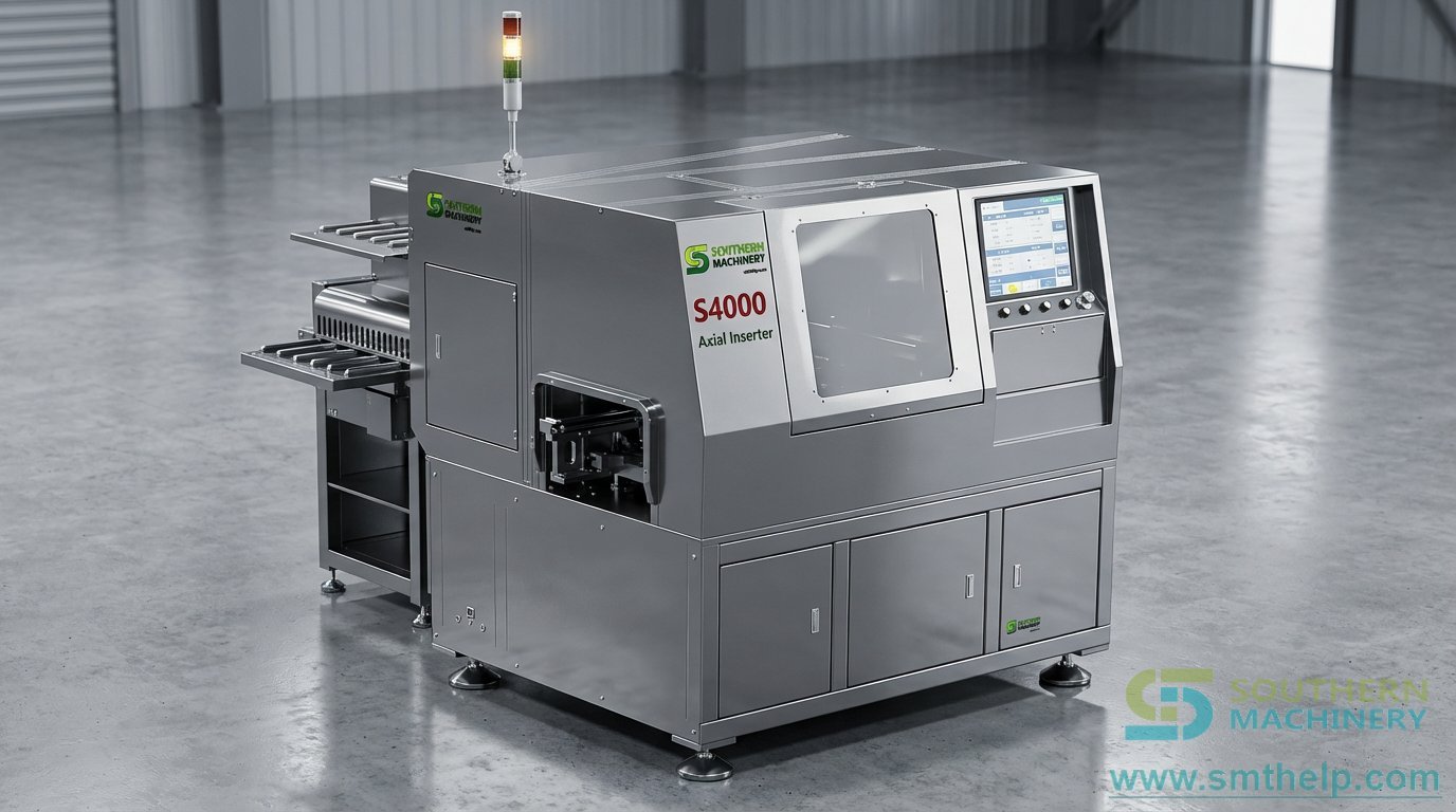
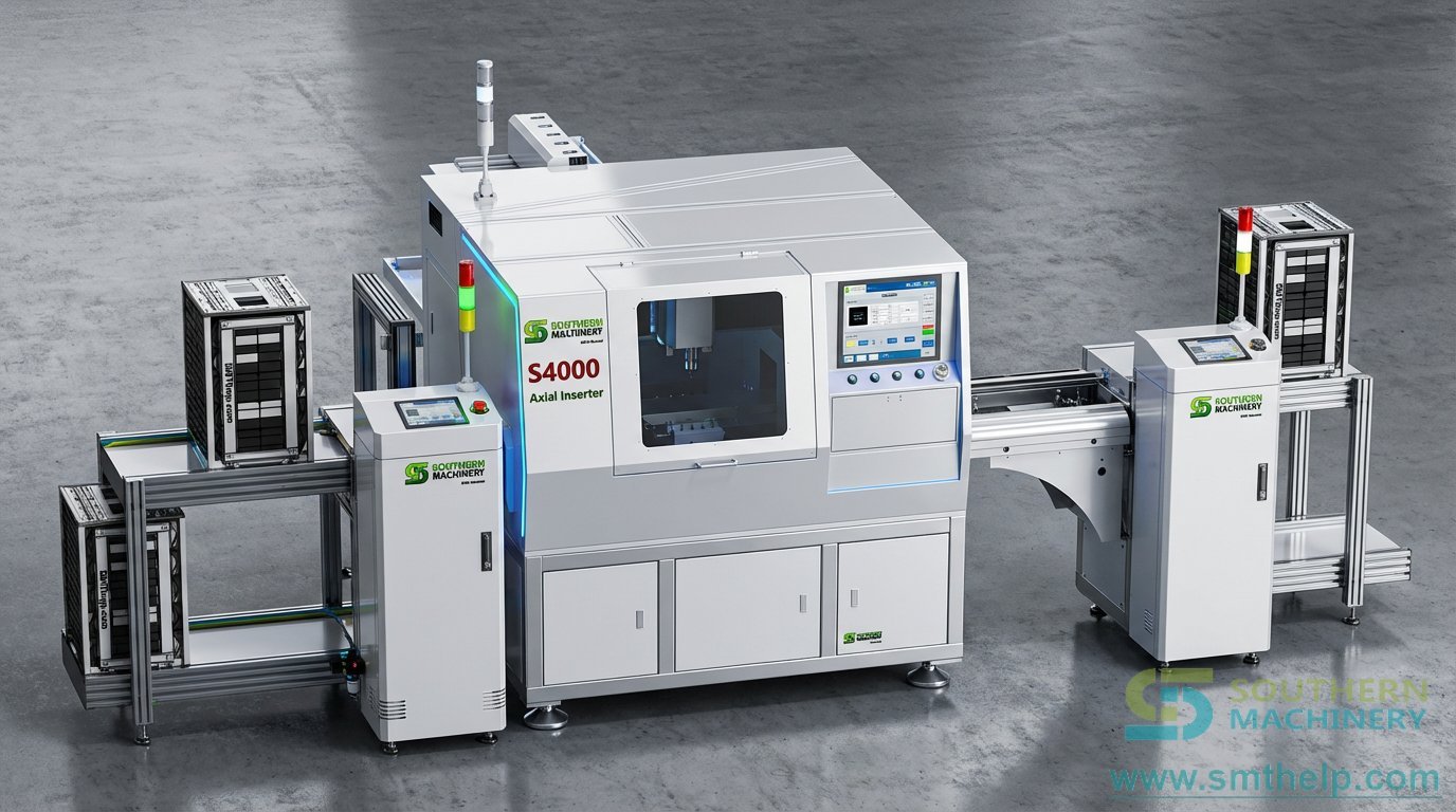
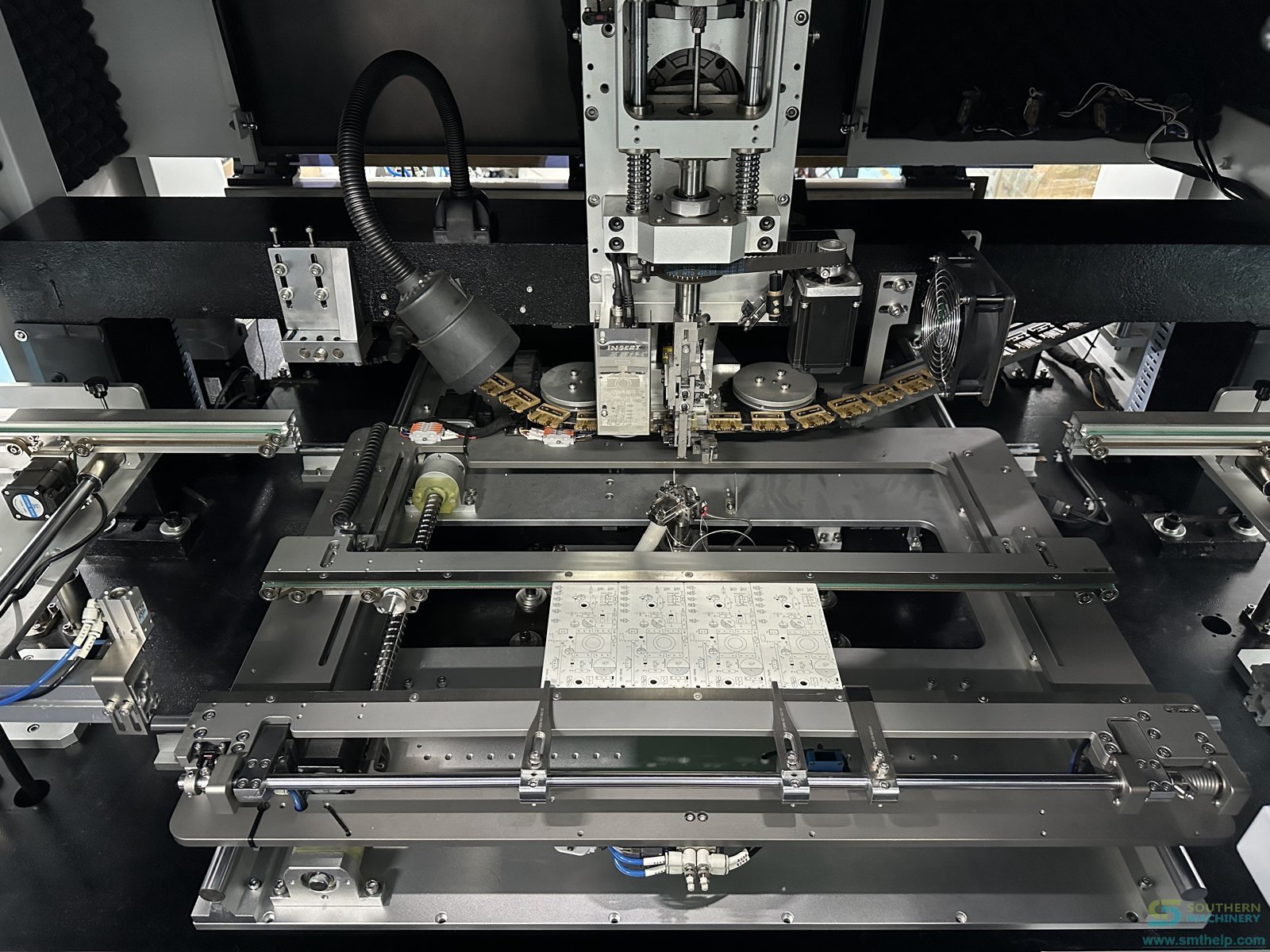
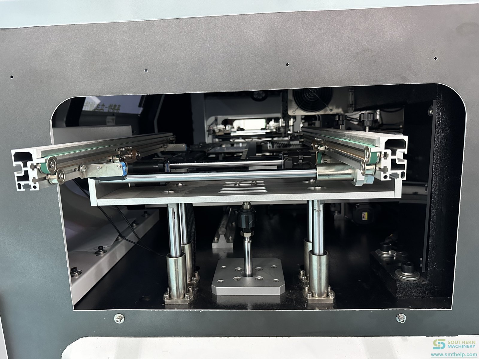
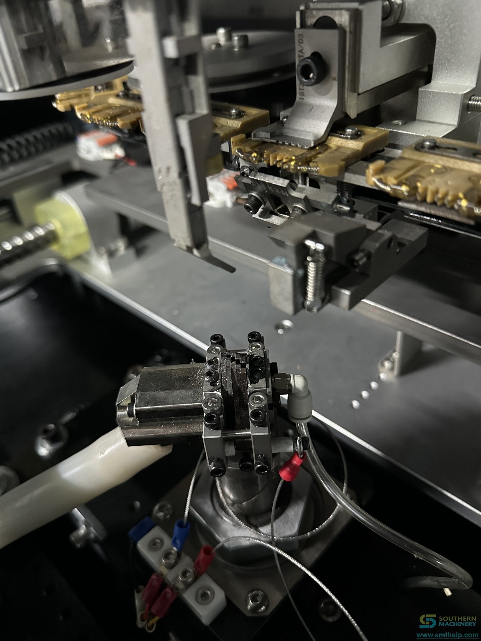
Watch the S4000 in production
From sample review to lifetime support
- 1 · Free demo — Free demo production with ten of your bare boards, live streaming of the run and a written evaluation report.
- 2 · Configuration and quote — Feeder bank, jumper feeders and PCB loading matched to your part list and board.
- 3 · Installation and training — Free installation and training, on site or remote.
- 4 · Lifetime support — 7×24 worldwide support, 1-day lead time on spare parts and a 1-month customised solution.
Frequently asked questions
What is the real insertion speed of the S4000?
Southern Machinery publishes 20,000 CPH as the nominal speed. The 2024 brochure also prints 10,000 CPH as the actual speed, which is the better figure for capacity planning. The rate for your own board is measured on a free demo run.
Which components can it insert?
Taped axial components such as resistors and diodes, and jumper wire, with lead diameters from 0.3 to 0.8 mm and lead spans from 5 to 22 mm. Axial parts and jumper wire can be inserted in the same program, or jumper wire on its own.
Which insertion angles are supported?
0°, 90°, 180° and 270°.
Can it handle two jumper wire gauges?
Yes, with the dual jumper feeder option, which runs two wire specifications such as 0.5 mm and 0.6 mm without a changeover, from reel or drum packages.
How many feeder stations do I need?
The feeder bank is modular and is sized to the number of axial part numbers across your product family. Send the part list and we confirm the configuration on the quotation.
Is it ready for MES?
The Windows-based control writes production data to an MES-compatible folder; 4G IoT and black-box data logging are listed as available. Programs are imported over USB in Excel format.
What does the free demo involve?
Send ten bare PCBs, the axial component list and your monthly volume. We run the boards, stream the machine live and send a written evaluation report.
What should I send with an enquiry?
The axial component list with lead diameters and spans, board size and thickness, and monthly board volume. A board drawing helps.
Engineering Review
Send PCB details for a practical machine recommendation.
Useful details: PCB type, board size, component list, monthly volume, current worker count, line layout and target automation goal.
Next step: Send the axial part list with lead diameters and spans, board size and thickness, and monthly volume. We size the feeder bank and give you an insertion time for your board.
Engineering Review
Send PCB details for a practical machine recommendation.
Useful details: PCB type, board size, component list, monthly volume, current worker count, line layout and target automation goal.
Send the axial part list with lead diameters and spans, board size and thickness, and monthly volume. We size the feeder bank and give you an insertion time for your board.